Yard Machines Y25 Manuel de l'opérateur

Naviguer en ligne ou télécharger Manuel de l'opérateur pour Tondeuses à gazon Yard Machines Y25. Yard Machines Y25 Operator`s manual Manuel d'utilisatio

  • Télécharger
  • Ajouter à mon manuel
  • Imprimer
  • Page
    / 12
  • Table des matières
  • DEPANNAGE
  • MARQUE LIVRES
  • Noté. / 5. Basé sur avis des utilisateurs
Vue de la page 0
PART NO. 769-05370 P00 (12/09)
Insert 10' of 0.080"SplitLine
®
through
hole in top of reel. Pull most of line
through hole until 3"-4" remains.
Wind line tightly in direction of arrow.
Split other end of SplitLine
®
back 6"-7".
Push 6"-7" ends into
0.080" holding slots.
Insert or slide lines into the
eyelets in spool. Insert spring
and reel into spool.
Pull lines firmly to release
from holding slots.
Bend short end and push it
into the other hole. Pull tight.
Bump
Knob
Inner
Reel
Spool
Spring
Press primer bulb 10 times.
Put blue choke lever
in Position 1.
Move blue choke
lever to Position 2.
While continuing to
squeeze the throttle
control, move the blue
choke lever to Position 3.
SQUEEZE and HOLD throttle
control for ALL further steps.
Pull the rope
5 times.
Pull the rope 3 to 5
times to start. Run
engine for 30-60
seconds to warm up.
Continue warming for an
additional 60 seconds.
During this time the unit
may be used.
Crouch in starting
position.
DIDN’T START?
Repeat these instructions.
If engine still fails to start, refer
to the Starting/ Stopping
instructions section of this
manual for additional starting
and troubleshooting information.
Quick Instructions to
Replace SplitLine
®
Trimmer Line
Replacement SplitLine
®
Part #49U0134K953
For single line installation,
refer to Line Installation
section of this manual.
For replacement spool
installation, refer to Installing a
Prewound Reel section of this manual.
Quick Instructions
to Start Engine
For complete instructions, refer to
Starting/ Stopping Instructions section
of this manual.
Quick Instructions to
Assemble Trimmers
For complete instructions, refer to the
Assembly Instructions section of this
manual.
Unscrew bump knob
counterclockwise. Remove
inner reel and spring.
5 X
3
"
-4
"
Hold the inner reel in place.
Tighten Bump Knob
clockwise.
IMPORTANT: READ OPERATOR’S MANUAL THOROUGHLY AND FOLLOW THE SAFE OPERATION PRACTICES BEFORE OPERATING THE UNIT.
1 Gallon 3.2 oz
40:1
Put D-handle on shaft. Move handle a
minimum 6 inches away from shaft grip.
Insert clamp bolt and tighten the wing nut.
Mix thoroughly in a separate fuel can:
– 3.2 fl. oz. of 2-cycle engine oil
– 1 gallon of unleaded gasoline
Place the unit on a level surface. Fill fuel tank.
NOTE: Do not mix directly in the fuel tank.
Read and understand all instruction, warning and danger labels on the unit.
Min. 6"
Bolt
Slide the slot in the cutting attachment shield onto
the guard mounting bracket and rotate it onto the
shaft. Push the square bolt through the shield and
bracket and thread it with the washer and wing nut.
Guard Mounting
Bracket
Wing
Nut
Washer
Español — Page 9 English — Page 2Français — Page 5
Operator’s Manual
DO NOT RETURN THIS PRODUCT
For Assistance, please call 1-800-800-7310 (U.S.) or 1-800-668-1238 (Canada)
or visit www.mtdproducts.com or www.mtdproducts.ca
NEED HELP? CALL 1–800-800-7310 IN U.S. OR 1–800–668–1238 IN CANADA
Y25
2-Cycle Trimmer
Vue de la page 0
1 2 3 4 5 6 ... 11 12

Résumé du contenu

Page 1 - Operator’s Manual

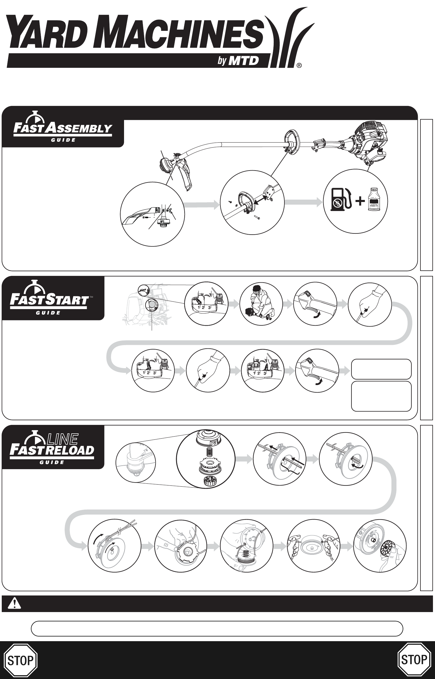
PART NO. 769-05370 P00 (12/09)Insert 10' of 0.080"SplitLine® through hole in top of reel. Pull most of line through hole until 3"-4&q

Page 2 - SERVICE INFORMATION

INSTALACION DE LA LINEAEsta sección cubre la instalación de la línea SplitLine™ y de la línea individual regular.Use siempre la línea de repuesto de 2

Page 3 - WARNING:

AJUSTE DEL CARBURADORLa velocidad mínima del motor puede ser ajustada. Puede tener acceso al tornillo de ajuste de mínima a través de unorificio en la

Page 4 - TROUBLESHOOTING

The limited warranty set forth below is given by MTD LLC (“MTD”) with respect with new merchandise purchased and used in the United States, its posses

Page 5 - AVERTISSEMENT

2• SAFETY AND INTERNATIONAL SYMBOLS •This operator's manual describes safety and international symbols and pictographs that may appear on this

Page 6

OPERATING INSTRUCTIONSHOLDING THE UNITBefore operating the unit, stand in the operating position (Fig. 7). Check for thefollowing:• The operator is we

Page 7

LINE INSTALLATIONThis section covers both SplitLine® and standardsingle line installation.Always use original equipment manufacturer 0.080 in.(2.03 mm

Page 8 - LLAMADAS A APOYO AL CLIENTE

5• SYMBOLES DE SÉCURITÉ ET INTERNATIONAUX •Ce manuel de l'utilisateur décrit les symboles et pictogrammes de sécurité et internationaux pouvant

Page 9

TENUE DE LA DÉSHERBEUSEAvant de faire marcher l'appareil, tenez-vous en position de fonctionnement (Fig. 7).Vérifiez les points suivants:• L&apos

Page 10

INSTALLATION DU FILCette section couvre l’installation de fil SplitLine™ et l’installation de fil simple standard. Utilisez toujours un fil deremplac

Page 11

LEA TODAS LAS INSTRUCCIONES ANTES DE OPERAR LA UNIDAD• Lea las instrucciones cuidadosamente. Familiarícese con los controles y el uso adecuado de la u

Page 12

• SIMBOLOS DE SEGURIDAD E INTERNACIONALES •Este manual del operador describe los símbolos y figuras de seguridad e internacionales que puedenaparece

Commentaires sur ces manuels

Pas de commentaire